5 Micron Filter Regulator 5 to 125 PSI and Lubricator 1 (F) NPT S51 AIRFLO 500
5 Micron Filter Regulator 5 to 125 PSI and Lubricator 1 (F) NPT S51 AIRFLO 500
Description
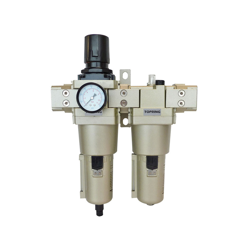
This FRL unit (filter, regulator and lubricator) for compressed air combines a 5-micron filter, a pressure regulator and a lubricator, providing a complete and compact solution for point-of-use air treatment. Its integrated design saves space while ensuring precise pressure control and consistent lubrication—both essential for the performance and longevity of pneumatic tools. It is also equipped with a semi-automatic drain, allowing simple and reliable condensate removal to maintain consistent system operation.
The push-pull adjustment knob allows easy pressure adjustment according to the requirements of the compressed air network. The 5-micron filter effectively removes particles and impurities, while the lubricator delivers a constant supply of oil to keep tools operating in optimal condition.
A pressure gauge is included for immediate visual pressure monitoring.
Pipe adapters and a wall bracket are also supplied for quick and simplified installation.
A high-performance and durable solution to optimize compressed air quality, reduce pneumatic tool wear and improve efficiency across industrial installations.
Technical Specifications
- Adjustability CapacityYes
- Bowl Capacity (L)0.13
- Bowl Capacity (ml)130
- Bowl or Reservoir MaterialAluminum
- ColorSilver
- Compatible FluidsAir
- Diaphragm MaterialEPDM
- Drain IncludedYes
- Drain LocationInternal
- Drain TypeSemi-Automatic
- Filter TypeParticulate
- Filtration Media or Strainer MaterialPolyethylene
Documents
There are no documents available.
Warranty
R1: 1 Year Repair
The repair warranty (R) means that the product or parts of the product will be repaired or refurbished. The warranty covers any manufacturing or material defect. The warranty does not cover installation and/or removal costs incurred by the customer nor shipping costs.
Failure to comply with the technical specifications, failure to follow the guidelines in the installation guide and/or the technical sheet, inappropriate or excessive tightening, misuse and/or abuse, failure to comply with the maintenance guidelines, normal wear, contamination and/or corrosion, neglect/accident, unauthorized repair attempt and/or disassembly, alteration of the product, assembly with incompatible products.
If the product contains one or several parts with a 1-month limited warranty (GL), these parts will be excluded from the 1-year warranty (R1).
See all the solutions offered by TOPRING to repair or replace the components of filters, regulators, and lubricators (drains, elements, bowls, pressure gauges, etc).
Disclaimer
Please note that while we make every effort to accurately represent our products on our website, slight variations in design and appearance may occur due to factors such as manufacturing processes and materials used.